Power Source Installation
The Dronetag BS unit is designed to operate with power inputs ranging from 3.3V to 17V. It employs a buck regulator mechanism to convert the incoming power to an internal voltage level. It's important to note that the power source chosen should be capable of handling peak currents of up to 50 mA at 3.3V.
The most commonly utilized sources for power input include the regulated voltage output from the flight controller. Alternatively, you have the option to utilize an aircraft battery, with support for up to 4S Li-Po configurations. For minimalistic usage, a compact external single-cell LiPo battery can also serve as a suitable power source for the device.
Using powerful batteries to power BS can potentially cause damage. Please read the Notice for products bought before 10/16/2023.
Where to Put Power Source?
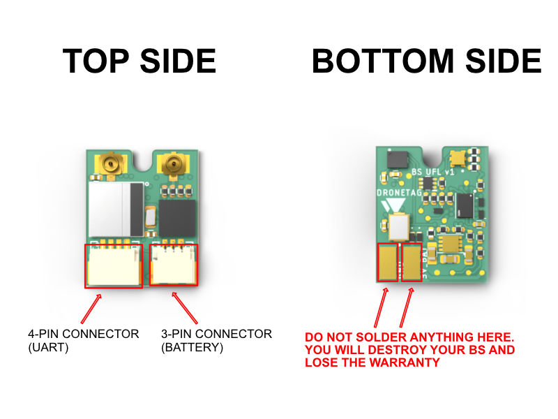
Dronetag BS has two connectors on the front side. Both of these connectors can be used as a power input, however, the use depends on your scenario. We have prepared the right 3-pin connector as a plug & play for our Li-Po battery. The use of the 4-pin connector on the left side for power supply is of course also possible, but it is necessary to follow the Wiring diagram below.
- Never supply both connectors with power input or you damage the device and connected power sources.
- Never use input voltage that falls outside the operating range of 3.3V to 17V or you damage the device and void the warranty.
- Never use the two soldering pads. Any attempt to use or solder anything onto these pads will result in irreversible damage to your BS device and will consequently void your warranty.
- BS lacks over polarity protection; connecting VCC and ground in reverse will result in irreversible damage.
Wiring Diagram
4-pin Connector (Placed on Left Side)
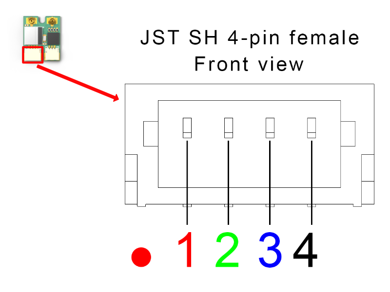
The connector placed on left side on Dronetag BS is a common JST SH 4-pin with UART interface with no flow control. This connector will be also used for support for Betaflight communication and Spektrum Telemetry XBUS in the future.
| Pin # | Name | Scheme Color | Description |
|---|---|---|---|
| 1 | VCC | Red | 3.3V to 17V. Directly connected to pin 1 at 3-pin connector |
| 2 | UART RX | Green | Receive of the Dronetag device (3.3V logic - 5V tolerant) |
| 3 | UART TX | Blue | Transmit of the Dronetag device (3.3V logic - 5V tolerant) |
| 4 | Ground | Black | Ground connection |
VCC pin 1 directly interconnected with VCC pin 1 at 3-pin JST SH (the other connector)
3-pin Connector (Placed on Right Side)
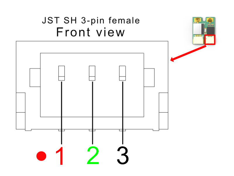
The connector placed on right side on Dronetag BS is a common JST SH 3-pin for powering the device and for communication with SRXL2-compatible devices.
| Pin # | Name | Scheme Color | Description |
|---|---|---|---|
| 1 | VCC | Red | 3.3V to 17V. Directly connected to pin 1 at 4-pin connector |
| 2 | RESERVED | Green | Reserved for SRXL2 support |
| 3 | Ground | Black | Ground connection |
VCC pin 1 directly interconnected with VCC pin 1 at 4-pin JST SH (the other connector)
Powering from Aircraft VIN
When choosing this type of power supply, you need to connect the BS with a cable to the power source. Always follow the rule that the power source chosen should be capable of handling peak currents of up to 50 mA at 3.3V.
Powered by External Battery
When an external battery is used, the Dronetag BS unit achieves full standalone functionality. Nonetheless, it's essential to consider the placement of the battery due to the current enclosure or heat shrink tube design limitations that prevent its accommodation. As a solution, you would need to create your custom enclosure, heat shrink tube, or mounting mechanism for the battery.
For your convenience, we offer a compact LiPo battery capable of powering the Dronetag BS unit for over 4 hours. This battery provides an excellent power source to ensure extended operational durations.
How to Use Battery charger
Operating with an input voltage of 5V, the charger maintains a charging current within the range of 50-200 mA. Adjusting the charging current is achievable through the soldering of specific jumpers on the charger's rear side. Connecting these jumpers together empowers you to enhance the charger's power output. It is imperative to underscore that any modifications in this regard are entirely your responsibility and should align with the specific battery you intend to charge. Please exercise the utmost caution, ensuring compatibility and implementing adequate safety measures during the modification process.
The board is also equipped with integrated circuits that offer protective functions, guarding the battery against overcharge, undercharge, and short circuits. Additionally, the board features a singular LED to indicate the ongoing charging status.