Diagrams
This page provides visual and technical references for the DRI module. In the first part, you will find diagrams illustrating the physical layout and position of key components on the module. The second part contains detailed specifications of the connector pinouts and supported communication protocols, ensuring correct integration with the flight controller and other onboard systems.
Highlight diagrams
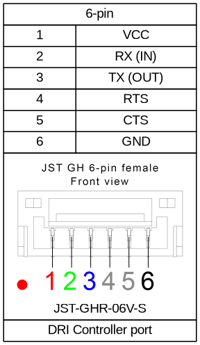
Flight Controller Port
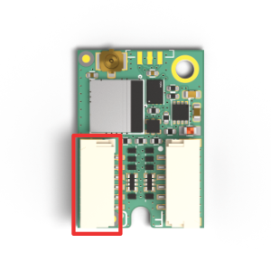 | Port designed to connect flight controller unit. For different integration wiring diagrams see section Integration |
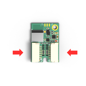
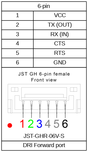
Flight Forward Port
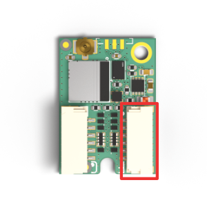 | Port designed to forward communication to the flight controller unit. To configure forwarding please see Configuration. |
LED Indicator
 | RGB led indication. For details please go to section LED Indications. |
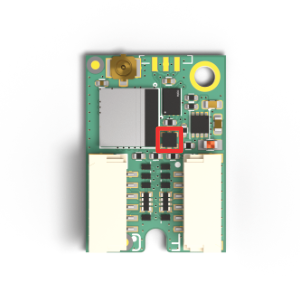
Antenna U.FL Connector
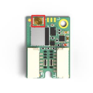 | U.FL series connector for external Bluetooth antenna. |
M2 Mounting Holes
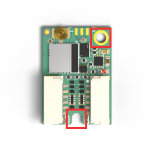 | Standardized M2 Mounting Hole. |
Wiring Diagrams
Operating voltage: 3.5V - 17V
Flight controller port (Port C)
Default settings:
| |
Forwarding port (Port F)
Default settings:
| |
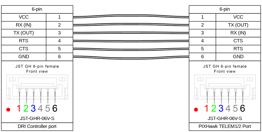
Pixhawk connection
Connect DRI to PixHawk TELEM port according to wiring diagram below.