Mounting the Scout
Choose the Right Location
Before installing the Scout receiver, make sure you have the proper location and infrastructure ready. This will save you time and ensure optimal performance from the start.
What You’ll Need for Installation
To install the Scout, make sure you have the following:
-
A tall structure or mast/pole - the higher, the better.
Ideally on the highest rooftop in the area, with a clear line of sight in all directions.
The Scout cannot receive signals through buildings or large obstacles. -
A stable power source:
- Either a standard indoor power outlet near the Ethernet cable entry point, or
- A PoE (Power over Ethernet) injector if direct power access is not available.
The Scout has a low power consumption (under 10 W), so both options are easy to accommodate.
-
An outdoor-rated Ethernet cable (CAT5 or higher) with the ability to crimp RJ-45 connectors.
-
Minimal radio interference: Avoid placing the Scout close to Wi-Fi transmitters or other antennas operating at 2.4 GHz or 5 GHz.
Drone controllers, mobile hotspots, wearables, and modern in-car Wi-Fi systems such as Apple CarPlay and Android Auto. Basically it is every device using wireless communication.
Recommended Conditions
For best performance:
- Choose a high, unobstructed position — the higher, the larger the detection range.
- Avoid areas with dense urban obstacles, metallic surfaces, or sources of RF noise.
- Ensure the Scout has a clear line of sight toward open space — it will not detect signals behind walls or buildings.
- If you are unsure about the right location, contact our support.
Send us the address of the intended installation site or photos from the rooftop view, and we’ll help you verify signal conditions using satellite data (e.g., Google Earth) and identify any potential interference sources.
Step-by-Step Guide
Now that your location is ready, the power and network connection are prepared, and you�’ve confirmed optimal conditions, follow these steps to mount and connect the Scout properly.
Carefully go through each step to ensure the best performance and long-term reliability of your installation.
Mount the Device
- To ensure optimal performance, the receiver should be mounted on an elevated structure like an existing pole, bracket, or mast.
- If no such structure is available, a tripod can be used.
Mount the device to the desired place. Remember, that the higher the place is, the better Scout will receive Remote ID signal coming from the drones. While mounting the Scout, stick with the mounting manual and strictly follow the local regulation for electrical installation and surge and lightning protection.
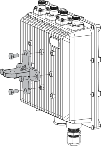
1. Fix a Cross Bracket to Scout
Fix the included cross bracket on the bottom of the enclosure with four (4) M6*12 bolts.**
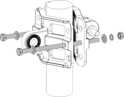
2. Mount the Pole Clamp
Place two (2) pieces of the clamp around the pole and tighten them with the included M6*110 bolts, washers, and nuts.**
3. Connect the pole clamp and Scout
The pole clamp works for 45 – 110 mm diameter of pole and the cross bracket by securing the last piece of the mounting kit in place using M6*30 bolts, washers, and nuts.**
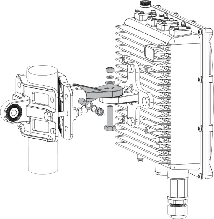
The Scout must be fixed so that antennas point perpendicular to the horizontal line.
Connect and Insulate the Cables
5. Connect the PoE cable
Please note that you will need the ability to crimp your own Ethernet cable with RJ-45 connector for any setup and connection.
Crimp your own Ethernet Cable
Use only CAT5 (or above) cabling with outdoor rating.
- The non-LTE version of Scout receiver must be constantly connected to an internet router for data transmission to the Dronetag Cloud when used in Cloud Mode.
- The Scout must be connected to the same network as the computer used to perform the initial configuration.
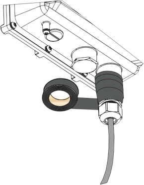
The receiver is designed for outdoor use, housed in a weather-resistant case. The Ethernet cable must be threaded through a cable gland and crimped inside for a secure connection.
6. Connect the ethernet cable using the PoE injector
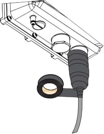
After the PoE cable is connected, insulate it with included PVC tape:
Insulate the Ethernet Cable Connector
- Clean the surface area of the connector that will be wrapped. Wrap a layer of PVC tape with a 50% overlap according to the rotation direction of the connector. Continue wrapping the PVC tape to about 10 mm below the end of the connector.
- Wrap three additional layers with PVC tape with natural uncoiling force and a 50% overlap. Make sure to cover the head and the tail of the connector.